
General Electric Power Generation Installation (Bangor, Maine) |
|---|
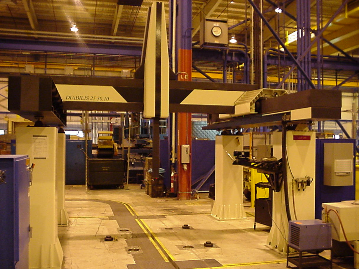 |
The Resource Engineering "DIABILIS" Gantry system is a 'shop-hardened' version of the popular open structure vertical spindle coordinate measuring machine, fully exploiting our Stabilis Technology.
The gantry support columns are fabricated from INVAR 36 low expansion alloy steel. The columns are finished by filling with an advanced polymer composite material for greatly increased vibration dampening characteristics and exceptional structural rigidity.
The longitudinal guideways are constructed from our patented CARBINVAR technology providing the perfect solution for dimensional stability in long fully-exposed guideways. The primary guideway has three faces precision ground and hand lapped to achieve exceptional accuracy for frictionless movement of the crossbeam on its air bearings while controlling the remaining five degrees of freedom. The secondary guideway of the same construction has the top face finished ground and hand lapped to support the crossbeam and eliminate roll over the full length of Y-Axis Travel
The Y-axis crossbeam is also constructed from our CARBINVAR technology and as with all REI moving elements is engineered to achieve the highest possible stiffness-to-mass ratio; maximizing accuracy and dynamic performance. The crossbeam is coupled to the primary longitudinal guideway through an INVAR fabrication providing a generous ratio between the spread of the main bearings and the length of the axis to control the pitch and yaw movements. The crossbeam provides travel for the X-Axis carriage and is supported by a pair of air bearings on the secondary longitudinal guideway. A second linear scale and drive system on the outside support is incorporated to eliminate the "crabbing" and bounce effect normally experienced with single drive gantry machines.
The "X" axis carriage is a spaceframe construction of Invar36 plate, utilizing a tab-n-slot construction technique fully welded and stress relieved. This provides the assembly with an extremely stiff, yet lightweight platform with which to traverse the crossbeam and support the vertical spindle ("Z" axis) assembly. The Z-axis Spindle is constructed from a square open section ultrahigh modulus carbonfiber composite structure, ground and lapped on all four sides. This spindle reciprocates through four pairs of diametrically opposed high-energy, matched air bearings mounted within the carriage structure. The PH10MQ indexing probe head or other sensors are attached to the end of this Spindle.
SAMPLE SPECIFICATIONS | ||||||
| Detail | REG30.25.15TD | REG40.25.16TD | REG40.25.20TD | REG55.35.25TD | REG90.36.24TD | |
| X | 3000mm/118" | 4000mm/157" | 4000mm/157" | 5500mm/216" | 9000mm/354" | |
| Y | 2500mm/98" | 2500mm/98" | 2500mm/98" | 3500mm/138" | 3600mm/142" | |
| Z | 1500mm/59" | 1600mm/63" | 2000mm/79" | 2500mm/98" | 2400mm/94" | |
| Resolution | 0.0001mm/0.000004" | |||||
| Repeatability | 0.003mm/0.00012" | 0.004mm/0.00016" | ||||
| Linear | X | 0.006/0.00032" | 0.008/0.00032" | 0.008/0.00032" | 0.011/0.00043" | 0.015/0.00059" |
| Accuracy | Y | 0.005/0.00020" | 0.005/0.00020" | 0.005/0.00020" | 0.007/0.00028" | 0.008/0.00032" |
| B89.4.1M | Z | 0.003/0.00012" | 0.003/0.00012" | 0.004/0.00016" | 0.005/0.00020" | 0.005/0.00020" |
| Volumetric Accuracy B89.4.1-1997 | 0.012/0.00047" 900mm/35" Ballbar | 0.015/0.00059" 900mm/35" Ballbar | 0.019/0.00075" 900mm/35" Ballbar | 0.027/0.00106" 900mm/35" Ballbar | 0.034/0.00134" 900mm/35" Ballbar | |
| U1 (VDI2617)* | 2+L/300 | 3+L/250 | 3+L/250 | 4+L/250 | 4+L/250 | |
| U3 (VDI2617)* | 3+L/250 | 4+L/200 | 4+L/200 | 5+L/200 | 5+L/200 | |
| Linear Vel. | 400mm per second/16" per second | |||||
| Max. ACC. | >1000mm per sec.2/40" per second2 | |||||
| Max. DeACC. | 1000mm per sec.2/40" per second2 | |||||
| Weight | 19,109 Kg. | 23,269 Kg. | 24,790 Kg. | 43,085 Kg. | 61,800 Kg. | |
| Approx. | 42,040 Lbs. | 51,193 Lbs. | 54,539 Lbs. | 94,787 Lbs. | 135,960 Lbs. | |