 |
| Supplier of UltraHigh Accuracy
Coordinate Measuring Machines and Ultrasonic Scanners! |
|
| Software by: |
 |
 | |
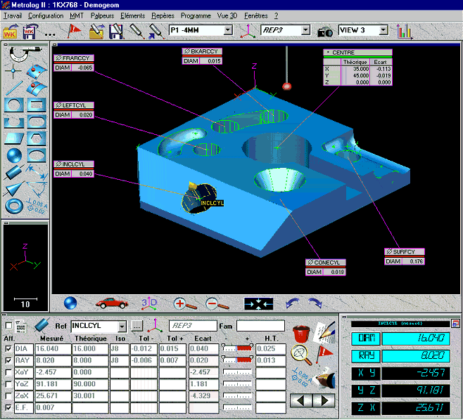
| Geometric Measurement: Metrolog II provides an interactive,
intuitive graphic interface to measure or construct features. Measuring
results and probe movements are displayed on screen in real-time. Features
can be clicked directly on the screen in order to construct other
entities. A detailed graphical display of geometrical features based on
probe points can be made. Optional software levels utilize CAD files such
as: IGES, CATIA ,VDA, UNISURF, SET, etc., for machine programming. |
| Surface Measuring: Applies to the analysis of a free-form part.
Here various types of CAD files are utilized. Surfaces, curves, Bezier or
rational entities and other imported entities can be displayed on screen.
Sections of the CAD file or unknown sections can be measured by scanning
in manual or automatic mode. |
| Alignments: Metrolog II allows several kinds of alignments:
model alignments, geometrical alignments, alignments using (6) surface
points or alignment on features. Probes are automatically calibrated when
using an indexable head. |
| Programming: Programming with Metrolog II permits teach
programming plus graphical off-line programming. Its immense flexibility,
permits ready modification of programs, enabling delete, copy, move or
paste. At any time you can intervene directly to change its composition:
x, y, z position, approach vector, projection surface for a point, etc.
Via points can directly be modified on the graphical view by click and
drag. The DMIS engine runs the native code avoiding post-processing
errors. Metrolog II lets you insert text messages, sound messages, photos
or graphics, all intended to assist the operator. |
| Statistics: Metrolog II allows for calculation and edition of
statistical results (average, standard deviation, capabilities, etc.) |
| Control Reports: User design of graphical and text reports with
stickers can be created according to the information you need to see. |
| Machine Interface: Metrolog II runs both manual and CNC machines
using our controls or those of other manufacturers. |
| Metrolog II calculates "real deviation" automatically, i.e.
the distance between the measured point and the projected point. It takes
into account the actual offset, material thickness and shrink factor.
While it selects the best projection surface automatically, it also lets
the operator choose from other possible surfaces. |
Metrolog II software is supplied in several levels. Each level provides
another step-up in functionality. All levels are embedded in the software and
can be "turned on" as your needs may demand. |
 |
 3D
Geometric Software for Prismatic Features 3D
Geometric Software for Prismatic Features
 Full
GD&T Capabilities (Geometric Dimensioning and Tolerancing) Full
GD&T Capabilities (Geometric Dimensioning and Tolerancing)
 Icon
Based Icon
Based
 Displays
Graphical Representation of a Features Form and Deviation Displays
Graphical Representation of a Features Form and Deviation
 Create
a Part Program Create
a Part Program
|
 |
 Level
I plus Graphical Interface Level
I plus Graphical Interface
 Full
GD&T Capabilities Full
GD&T Capabilities
 Create
a 3D Wire Frame (by Part or Print) Create
a 3D Wire Frame (by Part or Print)
 Create
a Part Program from Graphics Created Create
a Part Program from Graphics Created
 Build
a Program using Icons Build
a Program using Icons
 Internal
Graphics only Internal
Graphics only
 "Rubber
Band" Feature "Rubber
Band" Feature
 Optional
Off-Line Programming Optional
Off-Line Programming
|
 |
 3D
Free Form with Graphical Interface 3D
Free Form with Graphical Interface
 Basic
Element and Alignment Routines Basic
Element and Alignment Routines
 Ability
to Import and Export CAD Files (IGES, VDA, UNISURF, SET) Ability
to Import and Export CAD Files (IGES, VDA, UNISURF, SET)
 Reverse
Engineering Reverse
Engineering
 3D
Bestfit 3D
Bestfit
 Solid
or Wire Frame Graphical Representation Solid
or Wire Frame Graphical Representation
 Application
Specific to Free Forms Application
Specific to Free Forms
|
 |
 3D
Prismatic and Free Form Capability with Graphical Interface 3D
Prismatic and Free Form Capability with Graphical Interface
 Full
GD&T Capabilities Full
GD&T Capabilities
 Ability
to Import and Export CAD Files Ability
to Import and Export CAD Files
 Reverse
Engineering Reverse
Engineering
 3D
Bestfit 3D
Bestfit
 Solid
or Wire Frame Graphical Representation Solid
or Wire Frame Graphical Representation
 Optional
Off- Line Programming Optional
Off- Line Programming
|
|


 |
|
Published by Resource Engineering, Inc.
Revised: 21 Aug 2000 13:52:17 -0700
|

